Fig. 5.38: Sensing system
Microsystem development, miniaturization and integration demand more than purely electronic circuit simulator, since mechanical and electrical subsystems are to be fabricated together. Simulation of the complete system is often necessary and cannot be performed with a simulator solely dedicated to electronics or mechanics.
The system considered here is shown in Fig. 5.38.
Fig. 5.38: Sensing system
The pressure sensor is a capacitor, where the capacitance is dependent on a plate displacement, and this displacement is a function of pressure. In this example, the plate has circular shape. We presume quasi-static conditions and constant pressure all over the plate. A switched-capacitor pressure sensing system is given in Fig. 5.17. Cs is the sensor capacitance and Cr a reference capacitance.

Fig 5.39: Sigma-delta modulator
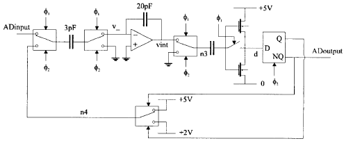
In real systems there is a need to have digital information about the voltage which refers to input pressure. Since we have discussed quasi-static conditions, the so-called sigma-delta modulator would be a convenient way to perform A/D conversion. Fig. 5.39 shows detailed scheme of a sigma-delta modulator.
When uniform signal is brought to the input, the converter gives the number of pulses proportional to the level of the input signal. The resolution of converted signal is proportional to a time spent in conversion. Logic state of the output signal makes decision whether the signal coming to integrator would be increased or decreased.
The sample and hold circuit as well as the binary counter are described behaviorally. Their structure is not of interest, but their existence is required. All the parts of the system work with a clock signal of 10Ás period, and sample and hold circuit has a clock pulse computed from:
SHclk = resolution · 10Ás
When resolution parameter is increased, the amount of time needed for gaining one value of pressure is also greater. Since we have discussed quasi-static conditions, this fact is not crucial.
Fig 5.40: Sensing system simulation results
The results of the simulation, when the pressure is monotone and rising, are given in Fig 5.40. The following variables are shown: input pressure signal; capacitance of the nonlinear capacitor; pressure sensor output signal; AD converter input held value; internal converter waveforms - voltage at the integrator output ( vint ), voltage at the input of flip-flop ( hybr ), returned value ( n4 ). Digital signals are: clk_sh - sample/hold circuit clock signal; clk - system clock; d - digital value of voltage at node hybr obtained at the output of automatically inserted A/D converter interface circuit; ADoutput - converter output; output [0] to output[4] - counter output signals. Counted values are marked below.
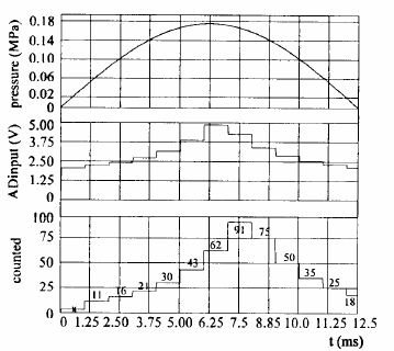
Fig. 5.41 shows the system response to sine input pressure, with resolution=100 ( ADinput is held value and counted is counter output). It is easy to observe mapping of sensor nonlinearity to the measured value.

Fig. 5.41: The sensing system response to the sine input signal